-
Why Choose
JSF Seismic Separator?
- With the development of U, V, and L types, there is a wide range of choices and applications.
- The structure is simple and the absorption of turbulent seismic motion is excellent.
- It is easy to install even in a narrow space.
- The thrust is small, so the design and auxiliary construction costs are economical.
- Excellent soundness by adopting a reinforced braid design.
- It is possible to install in all “±” directions of X, Y, and Z.
- It has been certified with a maximum pressure of 20K for displacements of ±25mm to ±610mm (the highest pressure and displacement in Korea).
- It is the only one in Korea selected by nuclear power plants, infrastructure, and major data centers, so it has high reliability.
-
INSTRUCTION
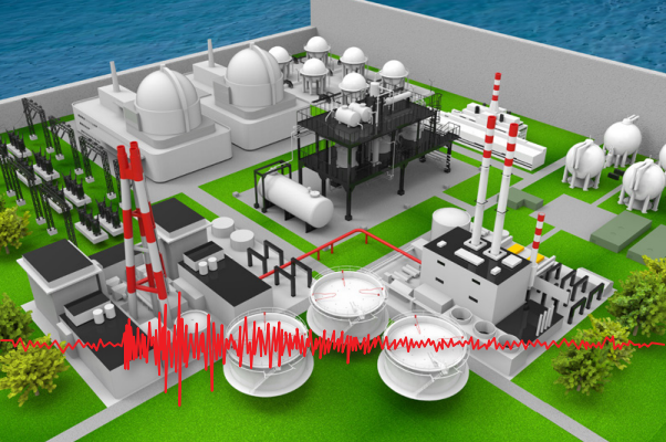
JRMS is the only company in Korea that has been selected and participated in seismic firefighting for nuclear power plants and thermal power plants.
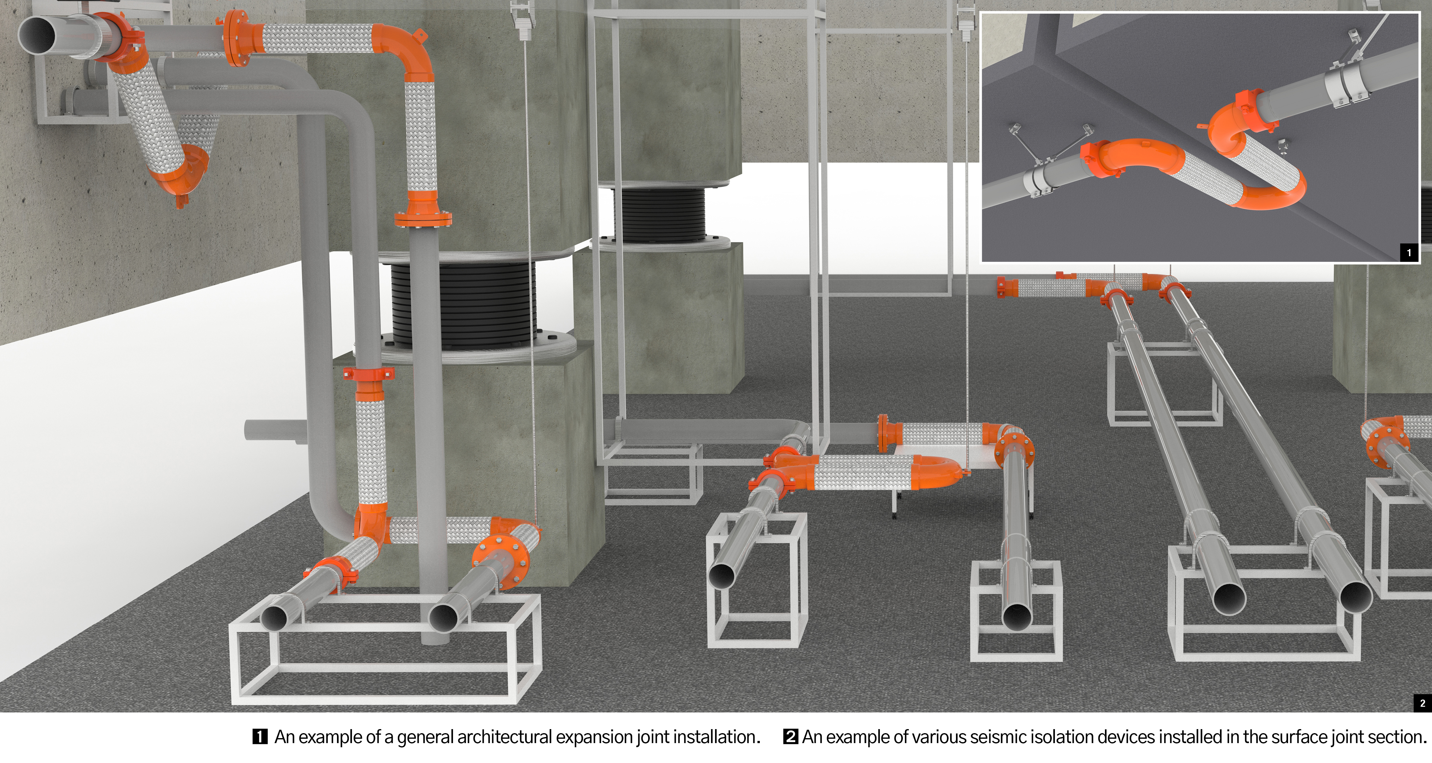
Installation purpose of seismic isolator
The seismic isolator measures seismic motion and its displacement in all directions of the piping in order to protect the fire-fighting system in response to the relative displacement occurring in the installation of seismic isolation joints in buildings and expansion joints or connectors connecting buildings in the event of an earthquake. refers to a device that absorbs or separates (isolates)
Legal installation location of seismic isolator
- Piping passing through the building's expansion joint
- Piping through buildings and skipping sections of buildings.
- Piping passing from the ground into the building.
- All piping passing through the seismic isolation section of a seismic isolation building
- Connecting piping for facilities that are concerned about damage due to earthquake motion, such as water tanks
JSF design and certification conditions
- Maximum operating pressure21 Bar (25A~200A), 18 Bar (250~300A), 12 Bar (25A~300A)
- Certified displacement±25mm, ±51mm, ±102mm, ±203mm, ±305mm, ±406mm, ±610mm
- Applicable connectorsWeld End (W1, W2), Flange End(F1, F2, F3), Groove End (G1, G2)
- Material of extension partBellows (S.S300 Ser.), Wire Braid (S.S304)
- Applicable piping materialKS & ANSI (C/S : SPP, SCH40 / S/S : SCH20S, SCH40S)
Various installation environment of JSF300 U, V, L
U-LoopVarious installation environments of JSF300 U, V, L The U-Loop Type of U-LoopJRMS is the most preferred type by customers, and when interference occurs in single or multiple piping as shown below, it can be installed according to the environmental conditions of the site by applying the Modifi-Type.
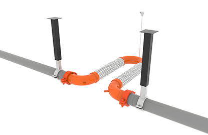 Horizontal installation
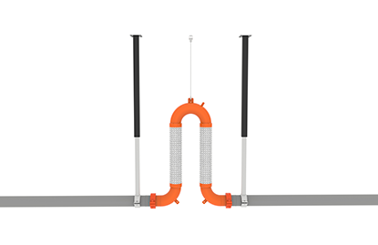 Upward installation
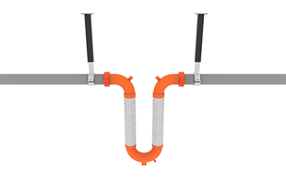 Downward installation
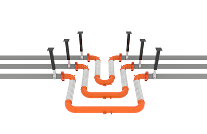 Dual-row U-Plus installation
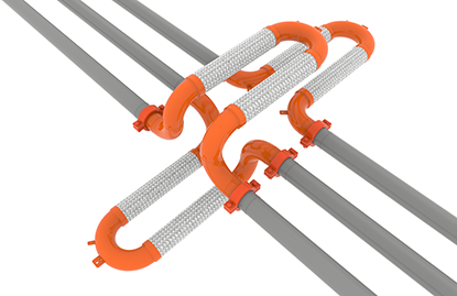 Duplex U-DB TYPE installation
V-LoopThe V-Loop Type of V-LoopJRMS has a lower head rate than other types, and can be effectively applied to single piping or multi-line double-row layouts without interference as shown below, making it easy to install in sections where complex double-row piping passes.
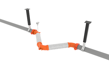 Horizontal installation
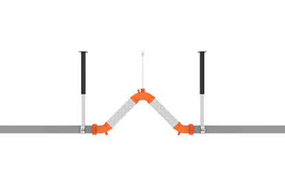 Upward installation
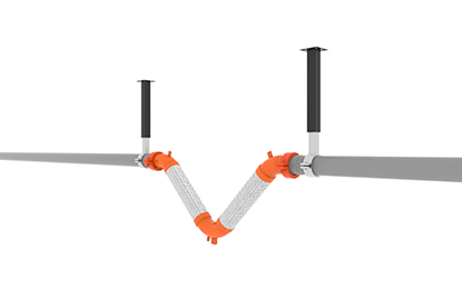 Downward installation
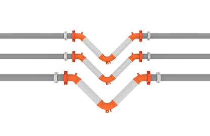 Horizontal double row installation
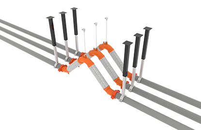 Up/down double row installation
L-Type(Dog-Leg) L-Type (Dog-Leg) The L-Type of JRMS is a type widely applied in Japan and Taiwan, and is also a type widely applied to seismic isolation sections of nuclear power plants and seismic isolation buildings in Korea. It is preferred for more economical installation than when applied to the building connection passage or the water supply inlet of the building.
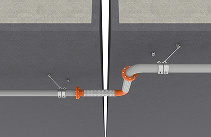 Horizontal installation
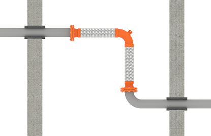 Upward and downward installation
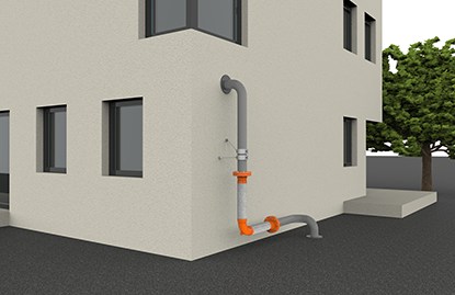 Indoor and outdoor installation at the entrance
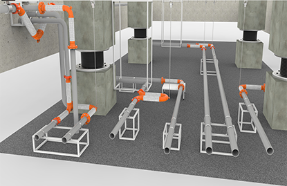 Seismic isolation building installation
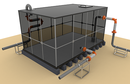 Installation of water tanks and facilities
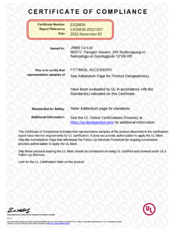
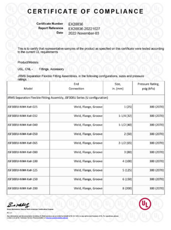
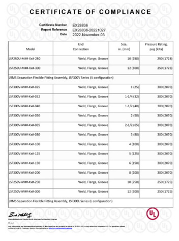
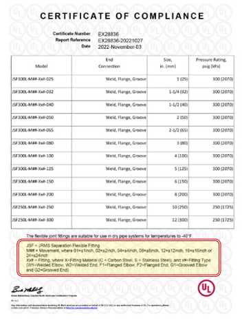
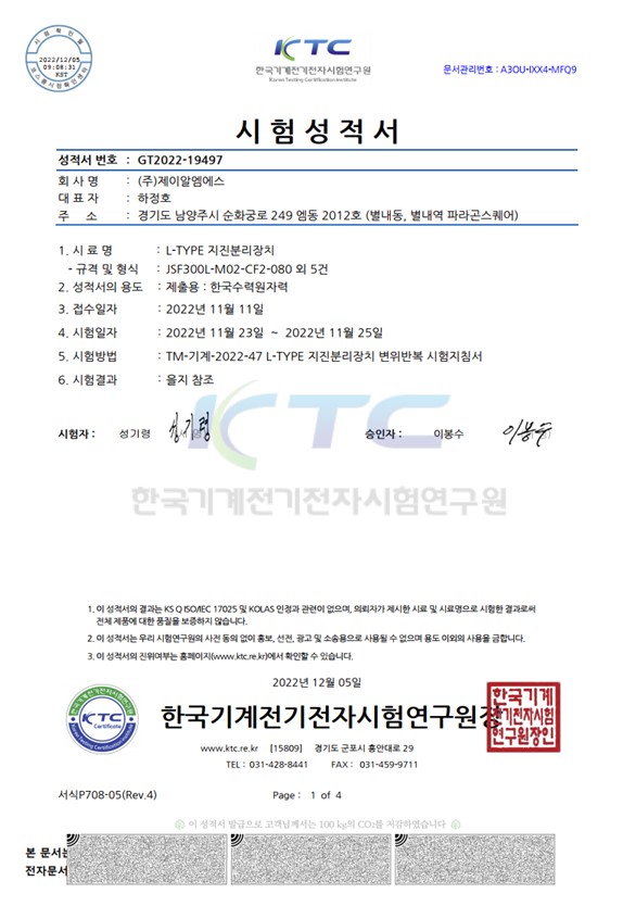
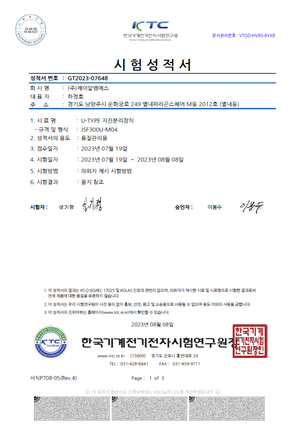
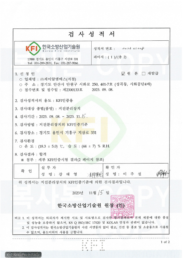
Certificate of Compliance

Certificate No.:EX28836 / Report:EX28836-20221027
- U type, V type, L type seismic separator
- Size25A~300A(1inch~12inch)
- Movement ±25mm~610mm(±1inch~24inch)
- END connection Weld, Flange, Groove
